
CNC Progress Report
In order to create parts that consistently have precise dimensions, we have decided to use a Computer Numeric Control machine or a CNC. This device can use a variety of rotating cutter heads such as routers and drills. We chose this based on the idea that it would be easier to follow the design sketches if we could easily make parts that were guaranteed to meet specifications. There are two programs that are required to achieve this. The first one is a CAD program that where one creates a sketch of the object to the exact final dimensions they want. Then one imports it to a MasterCam program to create the machining paths.

Outlined in white is the part that will be cut out of the stock material outlined in red.

Outlined in blue are the tooling paths the router will take to cut out the part in 3 dimentions. Multiple passes on each edge are required to avoid tear out and excessively wearing the tool.
For this part we decided to use a fairly wide router bit with a diameter of ¾ inches to provide a smooth angle of attack to avoid tear out on the white oak, which has an affinity for tearing out the grain. It’s also notable that we used climbing cuts on the all of the edges for the finishing cuts to again avoid tear out. As stated previously multiple passes were needed to make a full edge. Each pass usually took 0.2 inches off of the material. This was selected because it was less than half the diameter of the tool bit (0.75 inches) and it helped to avoid kick back that will be discussed later.

As one can see there is a lot of waste material on the edges of the stock. To avoid any kind of high velocity knockback of that waste, we decided to precut some of that waste off before we used the CNC.

Here the paler colored wood is the initial test we performed of the leg of the table. It’s cut to the exact dimensions of the design sketches. The darker piece of wood is a test run of the white oak that will be used in the table. It’s cut to be a ½ inch bigger in all dimensions than the paler wood. This increase of size is to avoid any kind of knockback by making all cut waste into harmless dust. This is a rough cut done by a band saw that isn’t to precise dimensions which is the CNC’s job.
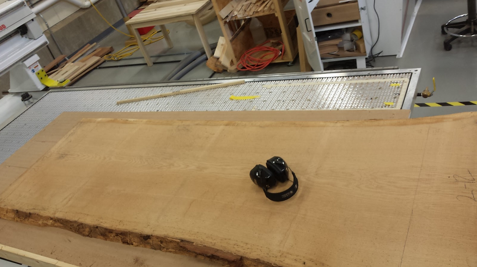
Here is a table top before being put through the CNC. Some of the table tops are far too large to be put through a planar. The CNC can plane a slab this large by running the router in a zig-zag motion taking layers off of some of the table. The table surface isn’t flat until a layer is taken off of the entire table. To preserve the thickness, structural integrity, and aesthetics of the table, we decided to not plane the underside of the table as it wouldn’t have any benefits.


